FAQs
- All
- AUTOMATION AND CONTROL
- CONTACTORS
- DIGITAL METERING INSTRUMENT
- ELECTROMECH. STARTERS AND ENCLOSURES
- ENERGY MANAGEMENT
- ENERGY METERS
- EXPANSION MODULES AND ACCESSORIES
- GENERAL PURPOSE RELAYS
- ISOLATION AND PROTECTION
- MICRO PLC
- MINIATURE AND RESIDUAL CIRCUIT BREAKERS
- MONITORING RELAYS
- MOTOR CONTROL AND PROTECTION
- MOTOR PROTECTION CIRCUIT BREAKERS
- MOTOR PROTECTION RELAYS
- PHOTOVOLTAIC APPLICATION
- PHOTOVOLTAIC APPLICATIONS
- ROGOWSKI COILS
- SOFT STARTERS
- SWITCH DISCONNECTORS
- TIME RELAYS
- VARIABLE SPEED DRIVES
The standard IEC / EN60947-4-1, referred to the contactor, of the contactors, prescribes that the operation of the contactors have to be within the temperature range of -5… + 40 ° C. In this temperature range the devices must guarantee correct operation with their maximum rated load. It is quite common for contactors to work over these temperature limits; this in consequence of the installation in extreme geographical environments or due to particular working conditions of the machine on which they are mounted. Lovato contactors can operate in the presence of higher or lower temperature in confront to the ones prescribed in the standard, in some cases a de-rating is necessary. Here below are some general indications about the behaviour of contactors in extreme temperatures ambient; we recommend that you contact our technical support for any clarifications for specific uses. Generally speaking, low temperatures do not cause electrical problems. The only case to take in consideration is the embrittlement of plastic materials; so shocks or wiring operations must be avoided when the equipment is in a very low temperature condition. Low temperatures do not cause deterioration of plastics or other components. Attention should only be paid to the use of electronically controlled
contactors in which some components may deteriorate if exposed to a lower temperature than the one indicated in the catalogue. High ambient temperatures are notoriously a problem because they are added to the normal heating generated by the contactor operation. Long periods of exposure to very high temperatures can lead to the permanent loss of mechanical properties due to thermal aging of the plastics. High temperatures influence the coil which can have an increase in the
resistance value, caused by the intrinsic property of the copper, which reduces the working performances. The terminals have a temperature increase due to the
passage of the current which, added to the ambient temperature, in extreme cases can lead to permanent deterioration of the properties of the plastics. In
general, in the presence of extremely high temperatures, these countermeasures can be considered: panel ventilation, contactor spacing to
avoid mutual heating and to facilitate heat dissipation and oversizing the contactors.
____________________________________________________
Other information on this topic
Visit the website page dedicated to contactors.
Check out our video tutorials BF series contactors accessories.
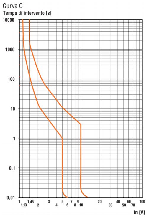
An MCB must protects against short circuits or sudden increases in the current absorbed by a load. The magnetic trip curves exactly define the protection behavior based on the amount of current to be interrupted. There are appliances (loads) that could give rise to untimely trips because when they start they have absorption peaks (eg. electric motors). In other cases the load could be very sensitive and not withstand even minimal current increases. To meet the various cases, the MCBs are
offered with different magnetic trip curves:
‐ C curve: trip in the range 5In ÷ 10In
‐ B curve: trip in the range 3In ÷ 5In
‐ D curve: trip in the range 10In ÷ 14In
C curve MCBs are the most used in installations without particular loads, those of B curve are suitable for the
protection of circuits with low inrush currents and for the protection of cables with considerable length. Finally, D
curve is used to protect loads with high insertion currents (motors, transformers, etc.).
Hereunder there is an example of an MCB curve with magnetic C curve:
________________________________________
Other information on this topic
Visit the website page dedicated to Miniature and residual circuit breakers.
Yes. The MCB offers protection against overloads for currents in the range 1.13In ÷ 1.45In. Since the overload is typically borne by most equipment, the trip is not
instantaneous.
‐ If there is a current of 1.13In, the switch must not trip before 60 minutes (In≤63A) or 120 minutes (In> 63A).
‐ If there is a current of 1.45In the switch must trip within 60 minutes (In≤63A) or 120 minutes (In> 63A).
‐ In case of higher currents the product standard establishes that the MCB has to trip within 60 seconds for a current equal to 2.55In.
Intervention times may appear long but take into account the need to avoid untimely trips due to overload situations that do not last over time.
___________________________________________________
Other information on this topic
Visit the website page dedicated to Miniature and residual circuit breakers.
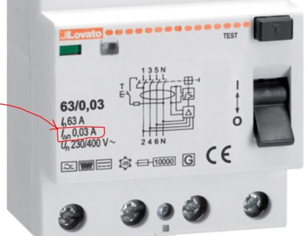 This data, indicated in the manufacturer’s technical tables, indicates the level of current protection offered by the RCDs. The sizes typically used in low voltage electrical distribution are 30mA and 300mA. Typically the 30mA
threshold is dedicated to the protection of people.
To explain the intervention thresholds, take the example of a 30mA RCD: this one will not trip only for leakage currents >30mA but in a threshold between 15mA and 30mA:
‐ for currents lower than 15mA the RCD will surely not trip
‐ in the threshold 15mA ÷ 30mA could trip
‐ for currents> 30mA it will trip instantaneously.
The central threshold (15mA ÷ 30mA) is a threshold with uncertain trip because the RCD, being an electromechanical device, cannot have a certain and fixed trip threshold.
________________________________________________________
Other information on this topic
Visit the website page dedicated to Miniature and residual circuit breakers.
AC type RCDs are only sensitive to sinusoidal type fault currents. A type RCDs, on the other hand, are sensitive to both sinusoidal currents and “unidirectional pulsed” currents, which may be present, for example, in systems with electronic devices for rectifying the current. These
devices are capable of generating pulsed‐shape fault currents with continuous components that an AC type RCD is unable to recognize. B type RCDs, besides being able to protect against sinusoidal and “unidirectional pulsed” fault currents, also protect against DC earth fault currents above 6mA DC. They also protect against high frequency fault currents.
_____________________________________________
Other information on this topic
Visit the website page dedicated to Miniature and residual circuit breakers.
The RCCBs, that means Residual Current Circuit Breaker, are automatic protections that cut the electric line on which they are installed in the event of a ground fault
(current leakage to ground). They are protections against indirect contacts.
___________________________________________________
Other information on this topic
Visit the website page dedicated to Miniature and residual circuit breakers.
The MCBs, that means Miniature Circuit Breaker, are automatic protections that cut the electric line for which
they are installed in the event of overload or short circuit.
___________________________________________________
Other information on this topic
Visit the website page dedicated to Miniature and residual circuit breakers.
 On the contactors the contacts are connected in series to increase the breaking capacity on DC loads; typically, more the load voltage increases, more contacts in series are needed to achieve an adequate breaking. The poles in parallel increase the current carrying capacity of the contactor. Take in consideration that the poles in parallel do not increase the breaking capacity; this in consequence of the construction tolerances that cause differences, although minimal, in the opening times of the various contacts in parallel. Practically the last contact that opens sustains almost completely the interruption.
The parallel connection of the poles is typically used to increase the rated contact capacity when the load is switched on and off by other devices. For example,
in the control of resistors where the command is given by static devices and the contactor is used just to obtain the galvanic separation of the load.
Consider that the contacts connected in parallel can’t sustain a current value obtained by the rated current of a single contact multiplied per the number of
contacts in parallel. A de-rating must be applied to consider the non-perfect distribution of the current between the contacts in parallel.
We will have to consider for 2 contacts in parallel a multiple of 1.6, for 3 contacts 2.2 and for 4 contacts 2.8.
For example:
If we have a contact with a rated current in AC-1 category of 25A, connecting 3 poles in parallel the rated current is 25×2.2 = 55A.
____________________________________________________
Other information on this topic
Visit the website page dedicated to contactors.
Check out our video tutorials BF series contactors accessories.
The utilization category specifies the nominal electrical performance of the contactor referred to a specific type of load. In the IEC / EN60947-4-1 standard, for each utilization category, the test conditions to which the contactor must be subjected to verify its operational effectiveness are prescribed. The most common utilisation categories for contactors are:
- AC-1 Non-inductive or slightly inductive loads (in practice resistance control)
- AC-3 Motor control
See the complete list at the bottom.
For example, if a manufacturer declares that a contactor has an AC-3 rated current of 9A at 400V means that this contactor can control motors with a
maximum rated current of 9A at 400V. The standard requires a long series of tests to confirm the conformity of the product to the control of such motors.
- AC-1 Non-inductive or slightly inductive loads; resistance furnaces
- AC-2 Slip-ring motors: starting, switching off
- AC-3 Squirrel-cage motors: starting, switching off motors during running
- AC-4 Squirrel-cage motors: starting, plugging, inching
- AC-5a Switching of electric discharge lamp controls
- AC-5b Switching of incandescent lamps
- AC-6a Switching of transformers
- AC-6b Switching of capacitor banks
- AC-8a Hermetic refrigerant compresso motor control with manual resetting of overload releases
- AC-8b Hermetic refrigerant compressor motor control with automatic resetting of overload releases
____________________________________________________
Other information on this topic
Visit the website page dedicated to contactors.
Check out our video tutorials BF series contactors accessories.
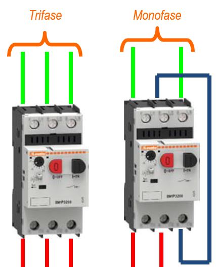
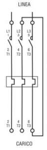
Yes, but a simple trick in the wiring must be implemented, that is, have the current pass through the three phases of the motor protection switch. In practice, a phase must pass through two poles of the switches connected in series between them.
Otherwise the motor protection switch will trip off due to thermal intervention. The motor protection switches are in fact sensitive to phase failure. Note that the same practice must also be implemented with thermal relays.
_______________________________________________________________
Other information on this topic
Visit the website page dedicated to Motor protection circuit breakers.
Check out our video
Check out our video tutorials
 |
|
|
|
|
|
|
|
|
|
|
|
|
TMM1NFC integrates 40 functions, included those of TMM1 (multifunction, 10 function), TMP (on-delay) and TMPL (flasher with independent timings).
Moreover, the numbering of the terminals of TMM1NFC, which is identical to the traditional versions with potentiometers above-mentioned, makes it perfectly
interchangeable with these models, without the need to modify the wiring diagram. Here are some useful tutorials that show ho to setup the TMM1NFC timer:
|
|
|
|
|
|
VIDEO TUTORIAL: How to use the counter function via NFC on the time – TMM1NFC |
|
|
VIDEO TUTORIAL: Setting function N “Hour counter” via NFC on the timer – TMM1NFC |
_______________________________________
Other information on this topic
Visit the website page dedicated to time relays.
Programming in simple and fast way, ideal solution for the programming of several time relays in series: you can program just one time relay and then copy the same programming on the others TMM1 NFC very quickly.
– Very high accuracy and precision in the time settings on the entire range (short and long scales), thanks to the setting in digital format.
– Repeatability of the settings: the programming downloaded in different TMM1 NFC is exactly the same identical, eliminating the risk of errors.
– Intuitive programming thanks to the graphical interface of the App which shows the diagram of the function that you are programming, without the need of the technical manual.
– Protection of the settings: possibility to protect the parameters configuration with a password, to prevent changes from unauthorized personnel.
– Flexibility: with NFC technology the number of the supported functions is not bound to the number of positions of the potentiometer but depends to the
dimension of the memory, allowing to obtain a greater number functions.
Here are some useful tutorials that show ho to setup the TMM1NFC timer:
|
|
|
|
|
|
VIDEO TUTORIAL: How to use the counter function via NFC on the time – TMM1NFC |
|
|
VIDEO TUTORIAL: Setting function N “Hour counter” via NFC on the timer – TMM1NFC |
_______________________________________
Other information on this topic
Visit the website page dedicated to time relays.
Yes, by default there are already three levels of access that you can view by following the path:
ProjectView> Security> doppio click su UserGroups

These three user groups cannot be deleted or renamed, however you can change the authorizations and other settings.
_______________________________________________
Other information on this topic
Visit our website and find out more on PLC and HMI.
Check out our video tutorials on HMI:
|
|
|
|
|
|
|
|
When the HMI is used as a data logger, the shortest sampling time is 0.1 seconds. It’s 1 second by default .
___________________________________________________________________________
Other information on this topic
Visit our website and find out more on HMI.
Check out our video tutorials on HMI:
|
|
|
|
|
|
|
|
When choosing the switch disconnector, the first thing to consider is the category of use, that is the application to which it’s intended. For example, the table below lists:
| AC-21 | Switching of resistive loads, including moderate overloads |
| AC-22 | Switching of mixed resistive and inductive loads, including moderate overloads |
| AC-23 | Switching of motor loads or other highly inductive loads |
The category of use actually determines which current must be considered.
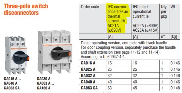
The conventional thermal current in free air Ith refers to the use of the appliance for continuous use without overheating beyond the limits allowed by the product standard, therefore its value is always greater than or equal to the maximum rated operational current Ie .
The rated operational current Ie, on the other hand, is the current value that the circuit breaker can bring into uninterrupted service based on the category of use.
In the LOVATO Electric offer, in most cases the value of Ie coincides with that of Ith, testifying to the high quality of the components used which ensure, with more demanding tests, such as AC22A and AC23A, performance similar to those in AC21A.
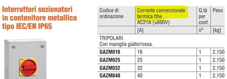
There is also a conventional thermal current in Ithe casing which is established by the manufacturer in relation to a specific enclosure where the device must be maintained. This is the case, for example, of switch disconnectors in metal enclosure:
__________________________________________________
Other information on this topic
Visit our website and find out more on switch disconnectors.
Check out our videos:
|
|
|
|
|
|
The category of use of a circuit breaker is defined by the product standard IEC/EN60947-2. This standard indicates 2 categories: A and B. Category A includes circuit-breakers without intentional tripping delays in the event of a shortcircuit, while category B includes circuit breaker with intentional tripping delays to guarantee selectivity. The motor protection circuit breakers must be in A category because they are designed to protect a single branch of an installation. Therefore they must not have delays to avoid the intervention of upstream circuit breakers that protect large sections of the system. This reduces the out of service to a single load on the line where the short circuit occurred.
_______________________________________________________________
Other information on this topic
Visit our website and find out more on Motor protection circuit breakers.
Check out our video
Check out our video tutorials
|
|
|
|
|
|
|
|
|
|
|
|
|
|
There is no predefined maximum number, theoretically it is unlimited. From a practical point of view, the limit is conditioned by the number of devices allowed by the network in which they are located (eg RS485 network) and by the possible traffic congestion on the network itself.
_______________________________________________
Other information on this topic
Visit our website and find out more on HMI.
Check out our video tutorials on HMI:
|
|
|
|
|
|
|
|
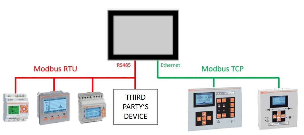
No, our HMIs can communicate with all devices that have an RS485 / 232/422 / Ethernet port and support Modbus-RTU Master / Slave, Modbus-TCP Client / Server, SIEMENS S7 Ethernet, MTTQ, or OPC UA Client / Server protocols.
_______________________________________________
Other information on this topic
Visit our website and find out more on HMI.
Check out our video tutorials on HMI:
|
|
|
|
|
|
|
|
Phase failure is a fault condition that can cause damage to the three-phase motor. The Lovato motor protection circuit breakers, SM series, are sensitive to phase failure and therefore save the motor from damages caused by this condition. It is possible to have two situations: phase failure at motor starting and phase failure when the motor is running. In the first case the motor usually can’t start. Staying locked with only 2 phases, a very high current is reached so the thermal protection of the motor protection circuit breaker will trip in a very short time. In the second case the motor continues to operate, but the phases that remain powered will draw a current that will be around 2 times the motor rated current with consequent overheating and the risk of burning. Furthermore, the motor working with 2 phases only can generate mechanical vibrations and consequent mechanical damage on the machine. In these conditions, the motor protection circuit breakers trip in a few tens of seconds which is an adequate time to avoid damage.
_______________________________________________________________
Other information on this topic
Visit our website and find out more on Motor protection circuit breakers.
Check out our video
Check out our video tutorials
|
|
|
|
|
|
|
|
|
|
|
|
|
|
![]() This type of undervoltage trip release has the purpose of removing voltage from the coil of the release itself when the motor protection circuit breaker is in OFF position. Otherwise the coil would remain permanently powered even if with the machine is stopped. Turning off the power supply to the undervoltage trip release reduces unnecessary energy consumption and consequent heating, moreover, in some applications, it allows the power to be removed from
This type of undervoltage trip release has the purpose of removing voltage from the coil of the release itself when the motor protection circuit breaker is in OFF position. Otherwise the coil would remain permanently powered even if with the machine is stopped. Turning off the power supply to the undervoltage trip release reduces unnecessary energy consumption and consequent heating, moreover, in some applications, it allows the power to be removed from
the auxiliary circuit connected in series to the undervoltage trip release (for example emergency buttons or limit switches).
_______________________________________________________________
Other information on this topic
Visit our website and find out more on Undervoltage trip releases and Motor protection circuit breakers.
Check out our video
Check out our video tutorials
|
|
|
|
|
|
|
|
|
|
|
|
|
|
Yes, all the parameters accessible from the display are also accessible via Modbus.
_______________________________________________________________
Other information on this topic
Visit our website and find out more on ADXL… series soft starters.
Check out our video
Check out our video tutorials
|
|
|
|
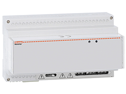
- The devices to be monitored must be equipped with RS485 or ethernet ports;
- EXCGLA01 must be connected to the local network (LAN), possibly by a static IP address or a dynamic IP assigned by a DHCP server where EXCGLA01 MAC address is coupled to a known IP;
- The IP address assigned to EXCGLA01 must be enabled to browse the internet if data transfer to remote servers is desired.
_________________________________________________________________________________________
Other information on this topic
Visit our website and find out more on Gateway data logger and energy management.
Make sure to visit em.lovatoelectric.com
Watch our video tutorials
|
|
|
|
|
|
|
|
|
|
The devices can be freely distributed between the RS485 and the ethernet port until the max number of 31 devices.
_______________________________________________________________
Other information on this topic
Visit our website and find out more on EXCGLA01.
Make sure to visit em.lovatoelectric.com
Watch our video tutorials
|
|
|
|
|
|
|
|
|
|
Synergy Cloud is reachable by EXCGLA01 at https://monitoring.lovatoelectric.com/api/gl/Excgla/Send.
_______________________________________________________________
Other information on this topic
Visit our website and find out more on Gateway data logger and energy management.
Make sure to visit em.lovatoelectric.com
Watch our video tutorials
|
|
|
|
|
|
|
|
|
|
It is necessary to verify if EXCGLA01 can reach the remote server. Check the set URL and run the dedicated test in “Administration area” section in EXCGLA01.
Furthermore, an account for a Synergy Cloud user must exist, being registered by the dedicated portal https://cloud.lovatoelectric.com the same credentials should be entered in EXCGLA01 as well in the relevant section “Administration area”/”Remote server”.
_______________________________________________________________
Other information on this topic
Visit our website and find out more on Gateway data logger and tenergy management.
Make sure to visit em.lovatoelectric.com
Watch our video tutorials
|
|
|
|
|
|
|
|
|
|
When the connection to a remote server is not possible or not required, EXCGLA01 offers the built-in web interface by which all data can be downloaded to
Excel or CSV files.
_______________________________________________________________
Other information on this topic
Visit our website and find out more on EXCGLA01.
Make sure to visit em.lovatoelectric.com
Watch our video tutorials
|
|
|
|
|
|
|
|
|
|
In case of new software releases of the applications loaded in EXCGLA01, the upgrade files should be downloaded from www.lovatoelectric.com in the product page. Run the following steps in sequence.
- Unzip the archive file and verify the presence of the following folder:
a. “updateV1.0_V2.1” folder.
2) Copy “src” and “Lovato” folders and 2 files in “updateV1.0_V2.1” folder to an empty USB memory; Attention: copy the “src” and “Lovato” folders and files only without “updateV1.0_V2.1” folder.
3) Insert the memory into the USB port of EXCGLA01; EXCGLA01 generates some different acoustic signals (beeps), until three consecutive beeps (end of upgrade); the update process can take up to 15 minutes. Remove the USB memory and switch EXCGLA01 OFF and ON.
4) Restart the browser on the PC; if the new application version is not shown (see below) at the bottom side of the page, press CTRL+F5 key combination to refresh the cache.
EXCGLA01 is ready with the new software version.
On USB memory a copy of the previous version is saved in “backup” folder, making it possible to restore EXCGLA01 at the point just before the upgrade operation.
_______________________________________________________________
Other information on this topic
Visit our website and find out more on EXCGLA01.
Make sure to visit em.lovatoelectric.com
Watch our video tutorials
|
|
|
|
|
|
|
|
|
|
Yes.
____________________________________________________________
Other information on this topic
Visit our website and find out more on PLC and HMI.
Check out Micro PLC user’s manual.
- The devices to be monitored must be equipped with RS485 or ethernet ports;
- EXCGLA01 must be connected to the local network (LAN), possibly by a static IP address or a dynamic IP assigned by a DHCP server where EXCGLA01 MAC address is coupled to a known
IP; - The IP address assigned to EXCGLA01 must be enabled to browse the internet if data transfer to remote servers is desired.
_______________________________________________________________
Other information on this topic
Visit our website and find out more on EXCGLA01.
Make sure to visit em.lovatoelectric.com
Watch our video tutorials
|
|
|
|
|
|
|
|
|
|
Yes, it is possible to do this by making a circuit outside the soft starter as indicated in the instruction manual
__________________________________________________________
Other information on this topic
Visit our website and find out more on ADXL… series soft starters.
Check out our video
Check out our video tutorials
|
|
|
|
 All kits are calibrated during the testing process by LOVATO Electric and come with the relevant calibration report. Kits don’t need calibration during their life in the electric plant.
_____________________________
Other information on this topic
Visit our website and find out more on Metering instruments and current transformers.
Make sure to visit em.lovatoelectric.com
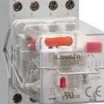 No, it is not, but it is warmly suggested. The relays are studied to stay firmly on the sockets without the clip in standard conditions, however, the clips guarantee a perfect stay in place even in case of heavy shock or vibrations. Consider not only the destination of the machinery or panel that could be without mechanical stress but also the transportation. The transportation on the installation place can be cause of heavy shock and vibration and the clips avoid any problem of relay
dropping.
____________________________________________
Other information on this topic
Visit our website and find out more on General purpose relays.
Cold and Hot do not refer to the ambient temperature at the installation point of the thermal overload relay. In fact, the Lovato relays are temperature compensated, so their tripping is not influenced by the ambient temperature for a range indicated in the catalogue (on average -15 ° C … + 55 ° C). Cold condition curve means that the relay has not been carrying a current for a period enough to allow the complete cooling of the tripping elements that are the bimetals. Hot condition curve means that the relay has been carrying the rated current set on the adjuster for a time enough to bring the bimetals into a condition of thermal regime. The time for complete cooling or to reach the thermal regime is around 60 minutes. So, if the relay is crossed by an overload current in cold condition, the tripping time will be longer than in hot condition. This is because in the hot condition the bimetals have already partially advanced towards the tripping point.
__________________________________________________________________
Other information on this topic
Visit the website page dedicated to Motor protection relays.
Check out our video
|
|
The accuracy of the measuring instruments is guaranteed within a range of current values indicated by the manufacturer. In particular, below the minimum value the instrument is no longer required to measure with the prescribed accuracy. It is therefore necessary to pay attention to situations in which the current absorbed by the loads varies frequently including the values below the minimum current, since even if they are the cause of an effective energy consumption, the measuring instrument could interpret them as “no load” and therefore does not count this consumption. It follows that two measuring
instruments in comparison, if equipped with different minimum current, can also provide significantly different energy values.
_______________________________________________________________
Other information on this topic
Take a look to the Metering instruments and current transformers web page.
Make sure to visit em.lovatoelectric.com
Yes, it is possible by considering the following requirements.
– It is necessary to use a variable speed drive with a rated output current greater or equal than the sum of all the rated currents of the motors controlled by the same drive.
– Each motor must be individually protected against overload, for example using a thermal overload relay selected according to the rated motor current.
– It is suggested to install a three-phase motor choke between the drive output and the motors.
________________________________________________________________________
Other information on this topic
Visit the website page dedicated to Variable speed drives.
Check out our videos
|
|
|
|
|
|
|
|
|
|
GA series switch disconnectors are compatible with GAX7… extension shafts with 5mm section. To use the GAX66N(B) handle with the GA030A, GA063 … 160A
disconnectors, however, it is necessary to use a GAX7…AN shaft with a 7mm section. In this case it is necessary to use the GAX60B accessory which adapts the hole for shafts with a 5mm section to those with a 7mm section.
______________________________________________________________________________
Other information on this topic
Visit the website page dedicated to switch disconnectors.
Check out our videos:
 |
|
|
|
|
BFD contactors are contactors specifically designed to interrupt DC loads. They find their major use in the photovoltaic applications, but are also suitable for any DC application such as railway traction, batteries control, telecommunication systems, DC drivers etc.
_________________________________________________________________________________
Other information on this topic
Visit the website page dedicated to contactors.
Check out our videos on BF series
|
|
|
|
|
|
|
|
|
|
|
|
|
|
TUTORIAL VIDEO: Assembly of mechanical restraint 11G222 |
|
|
In the construction of photovoltaic systems, international standards and national rules must be kept in mind. The national rules may have significant variations between different nations. However, the contactors in photovoltaic applications are typically installed immediately upstream and downstream of the inverter.
The contactor on the AC side is a common contactor that must be sized in category AC-1 or AC-3 according to the national regulation of the area in which it will be installed. The contactor on the DC side can still be a general purpose contactor if the voltage is under 400V. For sizing refer to the specific tables for DC use of the contactors shown in the Lovato catalogues. For voltages over 400V it is advisable to use contactors specially designed for DC applications.
These contactors have arc chambers equipped with permanent magnets that guarantee fast and effective interruption of the electric arc. Lovato BFD contactors have very high performance and can be used for voltages up to 1000V DC.
____________________________________________________
Other information on this topic
Visit the website page dedicated to contactors.
Check out our videos on BF series
|
|
|
|
|
|
|
|
|
|
|
|
|
|
TUTORIAL VIDEO: Assembly of mechanical restraint 11G222 |
|
|
The Hour counter function allows to count the working hours of a machinery and signal the reaching of a threshold by energizing the relay output, for example
to signal a request of maintenance. The hour counter (expressed in hours) is updated and saved in the memory of the TMM1 NFC every 10 minutes and compared to the other functions it remains stored even when the timer is powered off. To enable and configure the Hour counter function it is necessary to set:
– In the menu M01-GENERAL the function Hour counter, by setting P01.01=N
– In the menu M04-HOUR COUNTER the threshold to be reached in P04.01, expressed in hours.
Example. Configure the hour counter function to send a signaling after 200 hours of working.
Settings on TMM1 NFC via LOVATO NFC App:
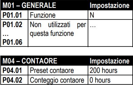
When the hour counter (P04.02) reaches the preset value (P04.01), the output contact of the TMM1 NFC is energized and it remains energized until the reset
command, which has to be manually done by closing the command input (S). From the LOVATO NFC App it is also possible to:
– monitor the current value (P04.02) of the hour counter
– modify the current value of the hour counter (P04.02), in order to anticipate the trip in case of necessity, without the need to wait for the remaining hours to reach the preset.
_____________________________________________________________________
Other information on this topic
Visit the website page dedicated to time relays.
Take a look to our video tutorials
|
|
|
|
|
|
 PMVFUPS01 accumulates enough energy (200Ws) to correctly drive PMVF series interface protection, a BF or B series contactor by LOVATO Electric acting as an interface switch and the shunt release of the backup. The selection of the right contactor according to the AC3 power is suggested on PMVFUPS01 user’s manual. In case of third party devices should consider that it can deliver a peak power of up to 1kW (1.25kVA) for 200ms during the switching on of the interface protection and peak power during the closing of the interface switch. Normally the back-up coil must not be powered, since the resetting of the back-up device is manual by standards and therefore must not open in the event of a power failure, but only on explicit command (shunt release) of the interface protection. With the system connected, therefore, the total absorption of the PMVFUPS01 loads consists of the sum of the power absorbed by the interface protection and by the interface switch coil in service conditions. The value should not exceed 25VA, which guarantees good operation even in the most critical condition allowed by the standards consisting of repeated voltage dips lasting up to 5s, even if this case is unrealistic. In case of doubts we recommend the use of devices with low consumption coils (AC/DC). For higher values or for more coils in parallel due to the presence of two or three interface devices driven by the same protection, it is necessary to consult LOVATO Electric technical support for a specific analysis.
_____________________________________________________________________
Other information on this topic
Visit the website page dedicated to Backup power supply for interface protection units.
A maximum time of 15s is required to fully charge the storage capacitors. The output voltage is present only when the charge is completed. It must be considered that the recharge is required at the very first switch on as well.
_____________________________________________________________________
Other information on this topic
Visit the website page dedicated to Backup power supply for interface protection units.
PMVFUPS01 guarantees the necessary energy by accumulating it in capacitors, thus avoiding the use of batteries which require maintenance.
_____________________________________________________________________
Other information on this topic
Visit the website page dedicated to Backup power supply for interface protection units.
Whenever the interface protection is installed as independent device from the photovoltaic inverter, the standards require an auxiliary power supply which supports the interface protection (IP), the interface switch (IS) and a possible back-up device in the event of a power failure.
_____________________________________________________________________
Other information on this topic
Visit the website page dedicated to Backup power supply for interface protection units.
Yes, they can. In the general catalogue, there’s a chapter dedicated to electromechanical starters and enclosures where the simple wiring to be carried out is indicated as:
____________________________________________________________________________
Other information on this topic
Please visit the web page dedicated to Electromechanical starters and enclosures.
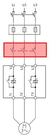
It is a contactor installed upstream the soft starter to warrant a galvanic separation between the power supply line and the motor when the motor is not in use (stop).
The presence of the line contactor is extremely important for the following purposes:
1.Safety of the personnel: it removes the voltage on the motor side when the motor is not in use. The leakage currents through the thyristors may lead to dangerous voltages on the load side when the soft starter is supplied.
2.Protection of the internal thyristors: the line contactor isolates the soft starter and protects the internal thyristors from any problems present on the network, like severe voltage spikes on the incoming line, such as lightning strikes or downed power line, etc… à possible consequences: damage of the thyristors (short circuit).
3.Disconnect the soft starter from the supply in case of fault:
−without a line contactor the soft starter can only detect a fault condition (e.g., thyristors shorted, bypass relay stuck, etc…) and provide signalization using fault relay (if available) but is not able to stop the motor despite the stop command from the logic input.
−there must be a device that will react on fault signal and stop the motor!
For the reasons outlined above, the presence of the line contactor on soft starters is mandatory. The standard prescribes only requirements for the protection against short circuit and protection of the installation. But for the reasons just given, a line or isolation contactor is strongly suggested even if not mandatory.
____________________________________________________
Other information on this topic
Visit the website page dedicated to contactors. Check out our video on BF series
|
|
Visit the website page dedicated to ADXL… series soft starters and check out related videos
Yes, it can be used circuit breaker with undervoltage trip.
In case of fault the soft starter will interrupt the signal on the breaker undervoltage trip through a relay output, with consequence interruption of the current flow to the motor. But contactor it is preferable due to its high mechanical durability compared with circuit breaker which is used for protection purpose not switching.
_________________________________________________________________________________
Other information on this topic
Visit the website page dedicated to contactors. Check out our video on BF series
|
|
Visit the website page dedicated to ADXL… series soft starters and check out related videos
|
|
|
|
|
|
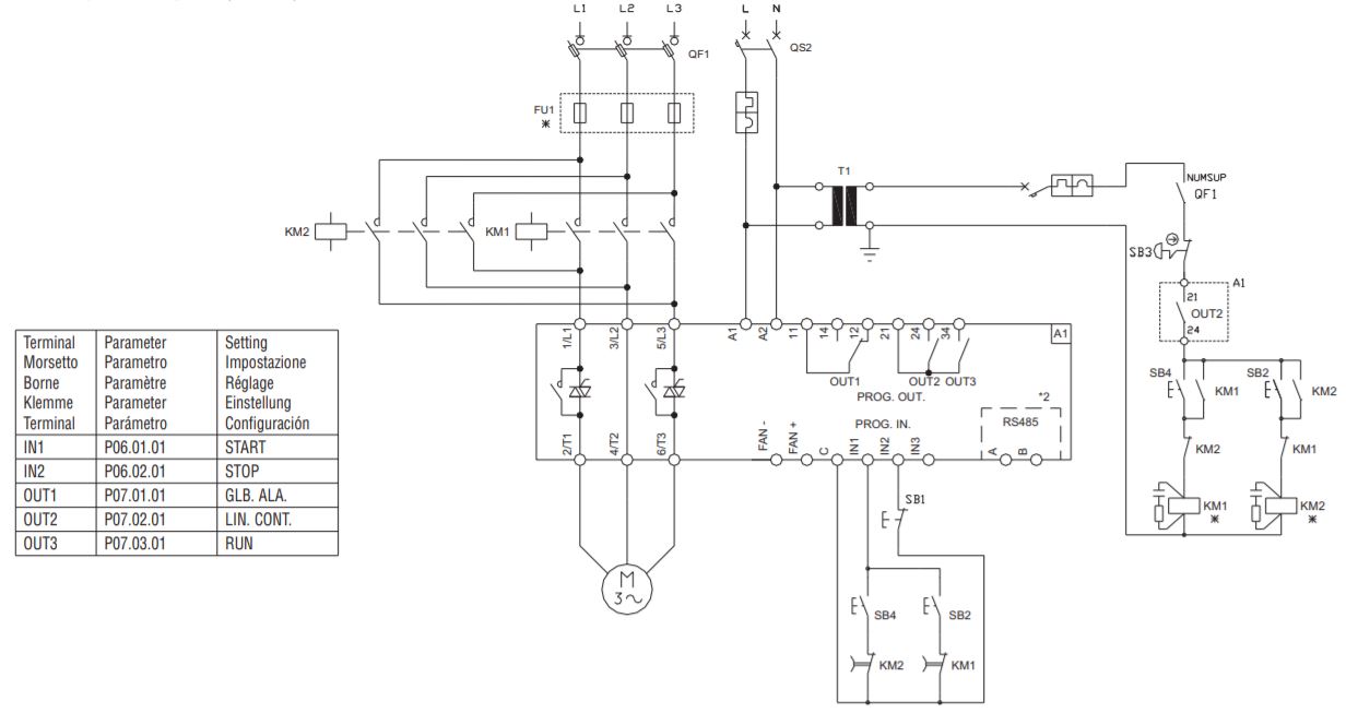
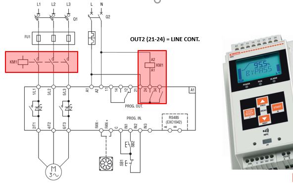
The command of the line contactor is managed automatically by the soft starter with a relay output programmed with the function LINE.CONT (sometimes also called Run according to soft starter models):
LINE CONT. = the output closes at the start command and it remains closed all the time when the soft starter is feeding voltage to the motor. It opens at the end of the deceleration ramp (or at the stop command in freewheel mode).

It keeps the line contactor energized as long as the motor is running, from the starting, up to the completion of the deceleration ramp.
Example. Line contactor managed with soft starter ADXL series
____________________________________________________________________________________________
Other information on this topic
Visit the website page dedicated to contactors. Check out our video on BF series
|
|
Visit the website page dedicated to ADXL… series soft starters and check out related videos
|
|
|
|
|
|
Bypass contactor should be AC-1 rated for the motor full load current (FLC) because it does not carry the starting current.

______________________________________________________________________________________________
Other information on this topic
Visit the website page dedicated to contactors. Check out our video on BF series
|
|
Visit the website page dedicated to ADXL… series soft starters and check out related videos
|
|
|
|
|
|
The line contactor must be sized in AC-3 category with a current greater or equal to the motor full load current (FLC).

Example
- Motor rated current = 28 A
- Soft starter rated current ≥ 28A AC-3 (e.g. ADXL0030600 à 30A)
- Line contactor ≥ 28A AC-3 (e.g. BF3200A230 à 32A AC-3)
________________________________________________________________
Other information on this topic
Visit the website page dedicated to contactors. Check out our video on BF series
|
|
Visit the website page dedicated to ADXL… series soft starters and check out related videos
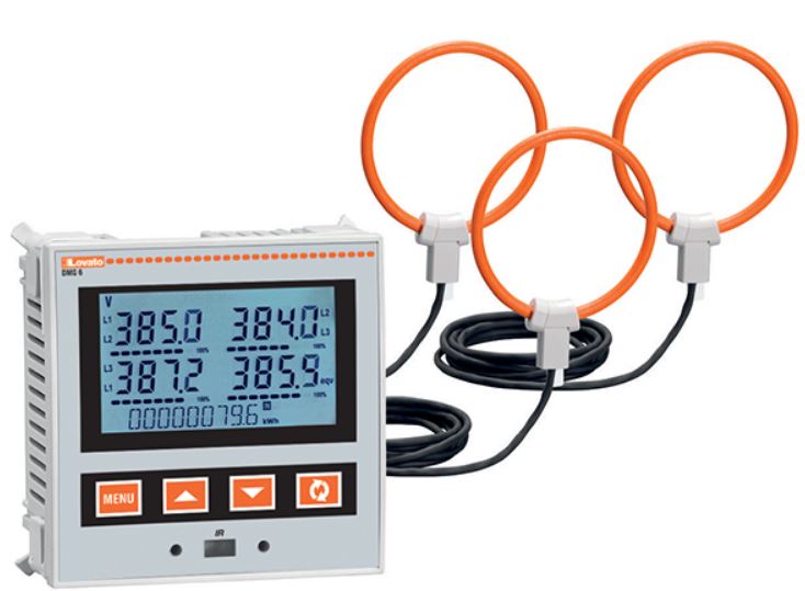
Two fundamental differences arise between a traditional split-core current transformer and a Rogowski coil, even if both of them are current transducers:
- the Rogowski coil is flexible and deformable, while a CT is rigid and non-deformable;
- considering the same primary current, the Rogowski coil occupies less space. For those reasons, the solution with Rogowski coils becomes profitable when an electrical panel upgrade is required and the available space is not large.
_____________________________________________________________________________
Other information on this topic
Take a look to the Metering instruments and current transformers.
Make sure to visit em.lovatoelectric.com
The output signal of a Rogowski coil must be processed in order to amplify, shift and filter it. Those operations are in charge of DMG611R… multimeter. The level of signal processing depends on each single coil piece, thus it is necessary that each measuring current input of DMG611R… is coupled and calibrated to get the best possible performance,
even in non-ideal coil installation condition (wire passage far from the centre). LOVATO Electric takes
care of that operation by making 100% of production of DMG611R… with calibration of the multimeter with
its three coils, offering a complete kit.
_______________________________________
Other information on this topic
Take a look to the Metering instruments and current transformers and to the dedicated brochure.
Make sure to visit em.lovatoelectric.com
In the kit made by the multimeter and the three Rogowski coils the calibration certificate elaborated by the calibration process is included. the certificate is
associated with the kit by reporting the serial number.
_______________________________________
Other information on this topic
Take a look to the Metering instruments and current transformers and to the dedicated brochure.
Make sure to visit em.lovatoelectric.com
The more the current to be measured is close to the maximum value which is readable by the coil, the more the accuracy and the linearity is guaranteed.
The cable is two meters long.
_______________________________________
Other information on this topic
Take a look to the Metering instruments and current transformers and to the dedicated brochure.
Make sure to visit em.lovatoelectric.com
The M series starters are composed of a contactor and thermal relay. To protect it against short circuits it is recommended to use fuses to be chosen according to the thermal overload relay current range. In the chapter of the catalogue dedicated to thermal relays are indicated, next to each code, the aM or gG type fuses that provide the correct protection. For those who want a complete starter with overload and short-circuit protection, we remind the version M2P00911…. that, in addition to the contactor, have a motor protection circuit breaker of the SM1R series inside.
____________________________________________________________________________
Other information on this topic
Please visit the web page dedicated to Electromechanical starters and enclosures.